Anwendungsbeispiele für Multipositionsventile
SD Flowpath Configuration - MW
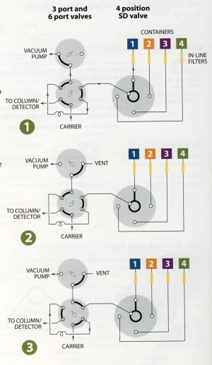
| SD valves
select one of 4 to 16 dead-ended streams. The selected stream flows from
the valve outlet to a sample valve, pressure sensor, detector, column,
etc. The same configuration may also be used to direct one stream to a
number of outlets for applications such as fraction collection. This example illustrates automated sampling of non-pressurized containers. 1) A vacuum pump is used CONTAINERS to move sample from the containers to a 6 port sampling valve. 2) The 3 port valve is used to block the vacuum flow through the sampling valve to allow the sample within the loop to equilibrate at atmospheric pressure. 3) The six port valve is then switched, injecting the sample. This method eliminates any possible effect from pressure differences among the containers, providing accurate and repeatable results. All three valves can be automated with air or electric actuators for unattended operation. The SD flowpath isolates the unselected sample streams, but the potential exists for extraneous sample or contaminants to be in the lines when containers are first connected. To avoid problems, either prepurge each line or allow sufficient sampling time for the line to purge prior to injection. |
 |
SC Flowpath Configuration - MW
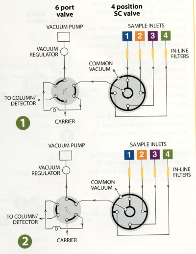
| SC valves
are similar to the SD configuration, except that instead of being
dead-ended the non-selected streams flow to a common outlet. They are
also available in 4, 6, 8, 10, 12, or 16 position versions. The SC configuration is ideal for air quality monitoring, illustrated in this example. The application is essentially the same as the one shown for the SD valves, except that the non-selected streams are continuously pulled through the valve, insuring that the most current sample will be provided as each point is selected for analysis. 1) The sample loop on the 6 port valve is loaded from Stream 1. 2) The six port valve is switched, injecting the sample. Both valves can be automated with air or electric actuators for unattended operation. |
 |
SF Flowpath Configuration - MW
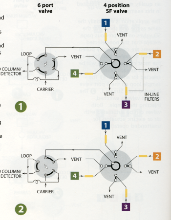
| SD and SC
valves select and isolate one of 4 to 16 streams, with the remainder
dead-ended in the SD and flowing to a common outlet in the SC. The SF is
similar, but carries the evolution a step further with the nonselected
streams flowing through individual outlets.
This is the ideal solution when
reactions or process streams with differing upstream pressures must be analyzed, and can also provide independent containment of toxic or noxious streams. An SF valve together with a 6 port sampling valve and pneumatic or electric actuators comprise a complete sampling system for the automated analysis of up to 16 sample points. Note that streams 1 and 4 are vented while streams 2 and 3 are returned to their sources in this example. Mode 1 shows sample loading from stream 4, while mode 2 shows sample injected onto the analytical column. |
 |
ST Flowpath Configuration - MW
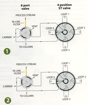
| ST valves
are used for multi-column, multi-sample, or multi-trap operations. The
ST configuration is available in
both MW and UW type designs.
A typical application, shown here, is the collection of fractions at timed intervals for analysis at a later time. Valves can be ordered with matched loops already installed. In this example, the 6 port valve shown is used to select between 1) collection / trapping and 2) analysis / desorption. Both valves can be supplied with pneumatic or electric actuators to automate these functions. |
 |
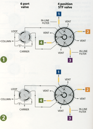
STF Flowpath Configuration - MW
| The STF
valve is a variation of the ST flowpath, with the single difference that
the non-selected streams are returned to their own vents or sources
rather than being dead-ended or trapped as they are in the standard ST
configuration. This is ideal for reactor processes in which removal of
substantial amounts of sample would upset the equilibrium within the
reactor, or if the stream is toxic or noxious and must be isolated. An STF valve on an air or electric actuator along with a similarly equipped 6 port valve comprise a complete sampling system for the automated analysis of up to 16 sampling points. |
 |
SD Flowpath Configuration - UW
| This example illustrates an SD (UW type) valve used for HPLC column selection. This allows multiple columns to be installed permanently in the system, eliminating instrument downtime and leakage potential resulting from having to change columns repeatedly. The SDUW valve selects only column inlets - the column outlets are connected to the detector via a lowvolume manifold. The manifold is sold separately. | 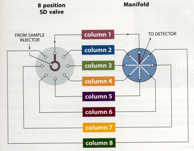 |
ST Flowpath Configuration - UW
| Column Selection with UW Type Valves Up to 6 HPLC columns can be rapidly accessed by column selection valves, eliminating instrument downtime involved in exchanging columns, and leakage due to repeated changing of tubing fittings. The columns are installed as a part of the loop system, as shown in this drawing. A 6 position valve can support 6 columns. | 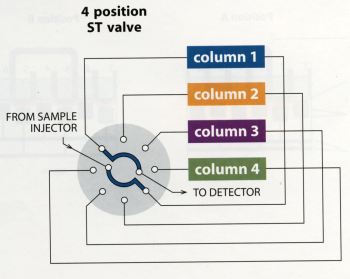 |